
UV water purification uses UVC radiation, most commonly at 254 nm, to inactivate target microorganisms as water moves through a properly designed and validated reactor.
For OEM equipment, performance depends on the required dose, design flow, UV transmittance, reactor geometry, lamp output, hydraulic conditions, and maintenance strategy.
LightSources co-engineers low-pressure, amalgam, and medium-pressure UVC lamps for municipal, industrial, residential, aquaculture, ballast-water, reuse, and high-purity water equipment. The lamp is one part of the final treatment system, so LightSources works with OEM teams to align the light source with electrical, mechanical, thermal, optical, and lifecycle requirements.
How Does UV Water Purification Work?
UV water purification works by exposing waterborne microorganisms to a controlled dose of germicidal UVC radiation that damages their nucleic acids and prevents replication.
Low-pressure mercury lamps emit primarily at UVC 254 nm, a wavelength widely used for water disinfection. The water flows past one or more lamps protected by quartz sleeves, and the reactor is designed to deliver the required exposure across the full hydraulic path rather than only near the lamp surface.
The final result cannot be predicted from lamp wattage alone. The EPA Ultraviolet Disinfection Guidance Manual treats flow rate, UV transmittance, UV intensity, lamp status, sensor performance, fouling, aging, and reactor validation as connected operating conditions. UV treatment also provides no downstream disinfectant residual, so drinking-water and reuse systems may require additional barriers or residual control based on the application.
What Determines the UV Dose Delivered in a Water Reactor?
Delivered UV dose for water treatment depends on the irradiance reaching the water and the time each portion of the flow remains within the effective radiation field.
For preliminary screening, dose may be expressed as irradiance multiplied by exposure time. A flowing reactor is more complex because the water follows multiple hydraulic paths, receives different irradiance levels, and may contain particles or dissolved material that absorb UVC. System design therefore has to account for dose distribution, not only an average theoretical value.
The main variables are design flow, minimum UV transmittance, lamp output at end of life, quartz-sleeve transmission, sleeve fouling, lamp spacing, reactor diameter, inlet and outlet geometry, sensor response, water temperature, and the selected validation method. The EPA UV Treatment Toolkit emphasizes that reactor flow must remain inside the validated envelope, and that lamp aging, sleeve fouling, and sensor-window fouling must be represented in long-term performance planning.
Which UV Lamp Technology Fits a Water Purification System?
The correct UV water treatment lamp technology is the one that can support the required dose, reactor footprint, power strategy, water temperature, service access, and validated operating range.
LightSources offers several UVC germicidal lamp families for water-treatment OEMs. Selection should compare the complete equipment requirements rather than treating higher lamp output as an automatic substitute for hydraulic design or validation.
| Lamp technology | Typical design fit | Engineering considerations |
| Low-pressure mercury | Residential, point-of-use, small community, process-water, and multi-lamp reactors. | LightSources low-pressure mercury lamps convert about 40% of electrical power to UVC at 254 nm. Their efficiency supports designs where the available lamp length and reactor footprint can accommodate the required lamp count. |
| Pellet amalgam | Municipal, industrial, aquaculture, wastewater, and compact high-output reactors. | LightSources pellet amalgam lamps provide up to 3x the UVC output of comparable standard lamps of the same length. The higher output can support more capacity or fewer lamps, but validated dose still depends on flow, UVT, geometry, fouling, and controls. |
| Medium-pressure UV | Compact, high-flow reactors and applications requiring high power density or broader spectral output. | LightSources medium-pressure lamps range from 100 to more than 700 watts per inch. The design must address power demand, heat load, cooling, sleeve conditions, ballast integration, and service intervals. |
| 185 nm option | High-purity-water and oxidation processes where 185 nm is intentionally used. | LightSources ozone-generating lamp envelopes pass 185 nm, while ozone-free options block 185 nm. The intended chemistry, materials, ventilation, and downstream process must be evaluated before specifying this wavelength. |
FAQs About UV Water Purification
How do open-channel vs. closed-vessel UV water systems differ in lamp selection?
Open-channel systems usually prioritize distributed lamp banks, hydraulic depth, fouling control, and service access, while closed-vessel systems prioritize compact power density, pressure-compatible geometry, full-pipe hydraulics, and sensor integration.
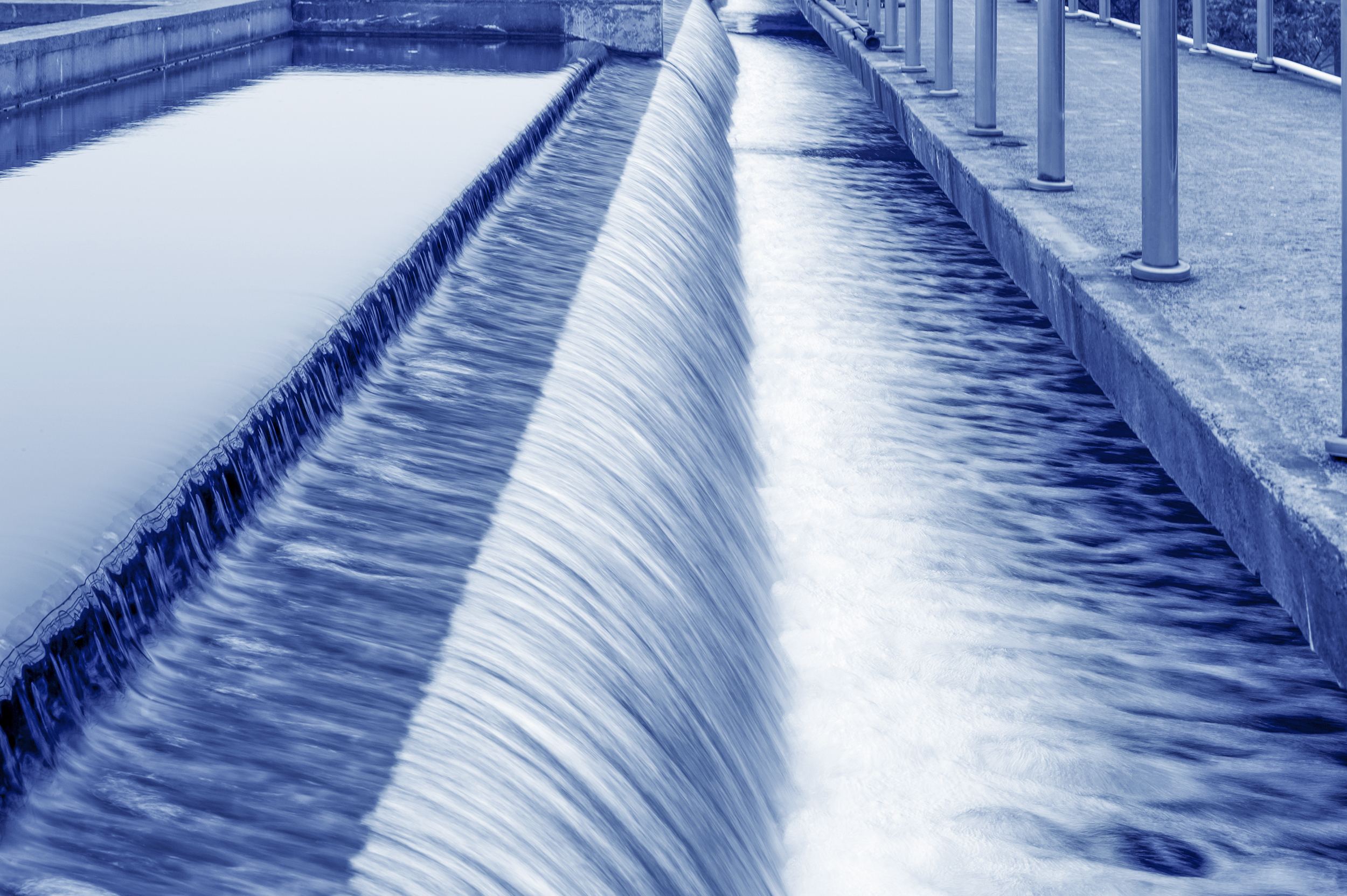
Open-channel UVC water disinfection is common in wastewater and reuse installations where water moves through a channel past submerged or sleeved lamp banks. Lamp length, bank spacing, channel depth, low-UVT conditions, automatic cleaning, and access for lamp replacement affect the configuration. A larger number of efficient low-pressure or amalgam lamps may be used to create a broad treatment field across the channel.
Closed-vessel reactors are used in pressurized drinking-water, industrial, residential, aquaculture, and process-water equipment. Lamp selection must fit the chamber diameter, pressure boundary, inlet flow profile, quartz-sleeve arrangement, sensor location, ballast controls, and available service clearance. Medium-pressure lamps may reduce lamp count in a compact footprint, while low-pressure high-output or amalgam lamps may reduce electrical demand when the reactor can accommodate additional lamp length or quantity.
How does flow rate influence UV dose in water reactors?
As flow rate increases, residence time generally decreases, so the reactor needs sufficient lamp output and hydraulic control to maintain the required validated dose.
Sizing should use the minimum, normal, peak, and upset flow conditions expected in the final equipment. Variable-flow systems may need staged lamp banks, variable lamp power, multiple reactors, recirculation, or a flow-control strategy so the reactor remains within its validated operating range. Low-flow operation also requires review because different hydraulics or excessive heating can move the equipment outside the conditions represented during validation.
For public-water applications, the EPA UV Treatment Toolkit states that the design flow rate should fall within the validated flow envelope and should reflect the facility capacity or the design rate of closely linked processes such as filtration.
How do you ensure uniform UV dose distribution in cylindrical reactors?
Uniform dose distribution in a cylindrical reactor requires optical and hydraulic design that limits short-circuiting, dead zones, swirl, shadowing, and major differences in exposure between flow paths.
Lamp number, arc length, sleeve diameter, radial position, chamber diameter, inlet and outlet orientation, flow conditioners, sensor placement, and the distance between lamps and the reactor wall all affect the dose field. Computational fluid dynamics and optical modeling can identify likely weak paths, but the final configuration should be confirmed through biodosimetry or another accepted full-scale validation method.
The installed piping must also reflect the conditions represented during validation. Upstream valves, bends, expansions, and reducers can change the velocity profile entering the chamber, so OEM documentation should define acceptable inlet and outlet conditions rather than treating the reactor as an isolated component.
What are the implications of RO and filtration pretreatment for UV performance?
Filtration and reverse osmosis can improve UV performance by removing particles, color, dissolved material, and scaling constituents that reduce UV transmittance or foul quartz sleeves.
The UV reactor still has to be sized from measured post-treatment water quality rather than an assumed improvement. Filter breakthrough, membrane damage, seasonal source-water changes, carbon carryover, and changes in temperature or flow can alter UVT and fouling behavior. Sensors and alarms should identify conditions that move the reactor outside the validated range.
In high-purity-water systems, 254 nm UVC may be used for microbial control, while 185 nm can support total organic carbon reduction when the process is designed for that purpose. LightSources provides additional guidance on UV TOC reduction in water, but the complete pharmaceutical or semiconductor water loop must be validated as an integrated process.
How is UV used in advanced oxidation processes?
UV advanced oxidation processes combine ultraviolet radiation with an oxidant such as hydrogen peroxide or ozone to generate highly reactive species that can transform certain dissolved organic contaminants. UV-AOP may be used for selected pharmaceuticals, pesticides, industrial solvents, taste-and-odor compounds, and other micropollutants that conventional biological or physical treatment may not adequately address. Performance depends on the contaminant chemistry, UV wavelength and dose, oxidant concentration, pH, UV transmittance, dissolved organic carbon, alkalinity, flow rate, and other constituents that consume reactive radicals.
Conventional UV/hydrogen peroxide and UV/ozone should not be presented as established stand-alone PFAS removal or destruction technologies because PFAS are highly resistant to oxidation. Specialized photochemical, photocatalytic, and advanced reduction processes are being studied for PFAS treatment, but these applications require validation of defluorination, transformation products, residual PFAS, energy demand, and performance in the actual water matrix. LightSources can support OEM developers with lamp wavelength, output, geometry, ballast integration, and prototype requirements for advanced UV water-treatment equipment, while final contaminant-removal performance must be established for the complete validated process. Learn more about UV Light in the Fight Against PFAS Contamination.
How do you select UV lamps for ballast water treatment on marine vessels?
UV lamps for ballast-water treatment must be selected as part of a complete, type-approved ballast-water management system and within the system’s approved flow, salinity, temperature, UVT, power, and operating limits.
Marine equipment adds vibration, shock, limited service space, variable water quality, corrosion exposure, power-management constraints, and the need for reliable monitoring and records. Lamp selection should address power density, warm-up and restart behavior, quartz-sleeve cleaning, ballast compatibility, cooling, redundancy, spare-lamp strategy, and replacement equivalency within the approved design.
The IMO ballast-water approval guidance ties approval to the specific system, treatment-rated capacity, operating ranges, test conditions, and limiting conditions. Changing the lamp, ballast, filter, or another major component can therefore require technical and regulatory review rather than a simple dimensional substitution.
How do you validate UV performance according to biodosimetry standards?
UV reactor performance is validated by operating the full-scale reactor under defined flow, UVT, lamp power, and hydraulic conditions while measuring the inactivation of a suitable challenge microorganism.
The measured response is converted to a reduction equivalent dose, then adjusted for uncertainty and any required validation factors. The resulting validated operating envelope identifies the combinations of flow, UV intensity or calculated dose, UVT, lamp status, and other parameters that support the treatment claim.
Validation should represent lamp aging, quartz-sleeve fouling, sensor response, inlet hydraulics, and the lowest intended operating conditions. The EPA Ultraviolet Disinfection Guidance Manual provides established drinking-water guidance for biodosimetry, reduction equivalent dose, validation factors, documentation, and validated operating conditions. Other applications may follow different regulatory or industry protocols, but the same principle applies: final reactor performance must be demonstrated under representative conditions.
Where are UV water purification lamps used?
UV water purification lamps are used in equipment ranging from residential point-of-entry units to municipal reactors, industrial process systems, aquaculture loops, wastewater channels, reuse systems, and marine ballast-water treatment equipment.
The application determines the target organisms, water-quality envelope, required dose, hydraulic configuration, monitoring strategy, and lamp technology. Related LightSources application resources include:
- UV drinking-water disinfection for municipal, community, well-water, and residential equipment.
- Industrial UV disinfection water treatment for process water and technical manufacturing applications.
- UV light for aquariums and aquaculture for recirculating systems, hatcheries, and aquatic-life equipment.
- Wastewater UV treatment for municipal UV water treatment and industrial effluent applications.
- Water reclamation for non-potable and potable-reuse treatment trains.
- Pool and spa UV treatment for recreational-water equipment.
- Ballast-water treatment systems for marine equipment subject to approved operating limits.
How does LightSources support UV water-treatment OEMs?
LightSources supports water-treatment OEMs by co-engineering the UV lamp and related interfaces around the final reactor, operating environment, production plan, and replacement strategy.
A successful lamp program begins with the water-system requirements, not a catalog part number. LightSources can support standard, modified, proprietary, private-label, second-source, and new-product programs through:
- Lamp-family selection and custom geometry for the required wavelength, output, arc length, orientation, and reactor footprint.
- Electrical and thermal integration, including electronic ballast matching and operating-condition review.
- Quartz-envelope and quartz-sleeve coordination for transmission, protection, fouling, and service access.
- Prototype development, lamp-level testing, change management, controlled manufacturing, and long-term replacement supply.
- Support for low-pressure, amalgam, and medium-pressure UV lamps used in water-treatment equipment.
LightSources supports OEM programs through ISO 9001:2015 registered manufacturing, the Rapid Prototype Program, and custom UV lamp design. Review the full OEM UV lamp engineering partnership and UV lamp engineering capabilities for additional program information.
OEM UV lamps for water purification systems
Effective UV water purification depends on the relationship among lamp output, reactor geometry, water quality, hydraulics, monitoring, maintenance, and validation. Selecting the light source early helps OEM teams coordinate footprint, ballast requirements, quartz protection, service access, and lifecycle supply before the reactor is fixed.
LAMP PRODUCT DATA:
LAMP APPLICATIONS:
LightSources helps OEMs align UVC lamp output, geometry, ballast compatibility, and lifecycle supply with final water-treatment equipment. ISO 9001:2015 registered manufacturing, custom engineering, and rapid prototype support help move programs from design into production. Contact LightSources to discuss OEM lamp support for UV water purification.
This post is also available in:
 Chinese (Simplified)